Valve
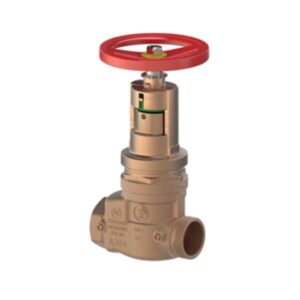
A204 Field adjustable pressure reducing valve
A204 Field adjustable pressure reducing valve
A204 Field adjustable pressure reducing valve
A204 Field adjustable pressure reducing valveA204Y001: Rough bronze
| Code | Size | BIM(revit) | CAD(dxf) | Certification | ||
|---|---|---|---|---|---|---|
| A204Y001 | 2 1/2″ NPT F x 2 1/2″ NST M | 1 | 0 | – | – |
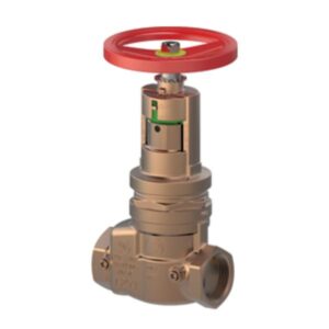
A203 Field adjustable pressure reducing valve, with checking device
A203 Field adjustable pressure reducing valve, with checking device
A203 Field adjustable pressure reducing valve, with checking device
A203 Field adjustable pressure reducing valve, with checking deviceA203Y001: Rough bronze
| Code | Size | BIM(revit) | CAD(dxf) | Certification | ||
|---|---|---|---|---|---|---|
| A203Y001 | 2 1/2″ NPT FxF | 1 | 0 | – | – |
A156 Pressure restricting valve
A156 Pressure restricting valve
A156 Pressure restricting valve
A156 Pressure restricting valveA156Y001: Rough brass
A156Y005: Rough brass
A156Y031: Polished brass
A156Y035: Polished brass
A156X001: Rough chrome
A156X005: Rough chrome
A156X031: Polished chrome
A156X035: Polished chrome
| Code | Size | BIM(revit) | CAD(dxf) | Certification | ||
|---|---|---|---|---|---|---|
| A156Y001 | 1 1/2″ NPT F x 1 1/2″ NST M | 1 | 0 | – | – | |
| A156Y005 | 2 1/2″ NPT F x 2 1/2″ NST M | 1 | 0 | – | – | |
| A156Y031 | 1 1/2″ NPT F x 1 1/2″ NST M | 1 | 0 | – | – | |
| A156Y035 | 2 1/2″ NPT F x 2 1/2″ NST M | 1 | 0 | – | – | |
| A156X001 | 1 1/2″ NPT F x 1 1/2″ NST M | 1 | 0 | – | – | |
| A156X005 | 2 1/2″ NPT F x 2 1/2″ NST M | 1 | 0 | – | – | |
| A156X031 | 1 1/2″ NPT F x 1 1/2″ NST M | 1 | 0 | – | – | |
| A156X035 | 2 1/2″ NPT F x 2 1/2″ NST M | 1 | 0 | – | – |
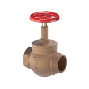
A86 Straight globe hose valve
A86 Straight globe hose valve
A86 Straight globe hose valve
A86 Straight globe hose valveA86Y001: Rough bronze
| Code | Size | BIM(revit) | ||
|---|---|---|---|---|
| A86Y001 | 2 1/2″ NPT F x 2 1/2″ NST M | 1 | 0 | – |
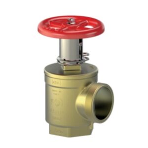
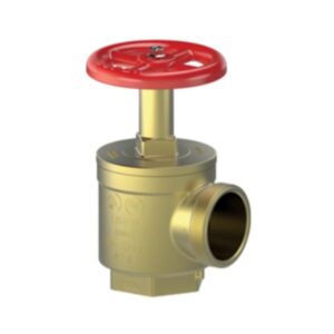
A56 Angle hose valve
A56 Angle hose valve
A56 Angle hose valve
A56 Angle hose valveA56Y001: Rough brass
A56Y005: Rough brass
A56Y051: Polished brass
A56TY005: Rough brass – With pin lug and cap chain
| Code | Size | BIM(revit) | ||
|---|---|---|---|---|
| A56Y001 | 1 1/2″ NPT F x 1 1/2″ NST M | 1 | 0 | – |
| A56Y005 | 2 1/2″ NPT F x 2 1/2″ NST M | 1 | 0 | – |
| A56Y051 | 1 1/2″ NPT F x 1 1/2″ NST M | 1 | 0 | – |
| A56TY005 | 2 1/2″ NPT F x 2 1/2″ NST M | 1 | 0 | – |
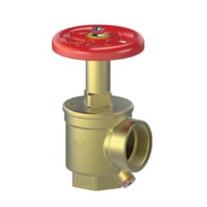
A50 Angle hose valve with hydrolator
A50 Angle hose valve with hydrolator
A50 Angle hose valve with hydrolator
A50 Angle hose valve with hydrolatorA50Y001: Rough brass – With hydrolator
A50X001: Rough chrome – With hydrolator
A50X011: Polished chrome – With hydrolator
| Code | Size | BIM(revit) | ||
|---|---|---|---|---|
| A50Y001 | 1 1/2″ NPT FxF | 1 | 0 | – |
| A50X001 | 1 1/2″ NPT FxF | 1 | 0 | – |
| A50X011 | 1 1/2″ NPT FxF | 1 | 0 | – |
A53G Single hydrant gate valve
A53G Single hydrant gate valve
A53G Single hydrant gate valve
A53G Single hydrant gate valveA53GY001: Rough brass – Pin lug swivel
A53GY021: Rough brass – Pin lug swivel with cap and chain
| Code | Size | BIM(revit) | ||
|---|---|---|---|---|
| A53GY001 | 2 1/2″ NST M x 2 1/2″ NST F | 1 | 0 | – |
| A53GY021 | 2 1/2″ NST M x 2 1/2″ NST F | 1 | 0 | – |
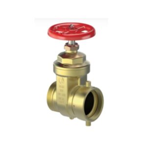
A53 Gate valve
A53 Gate valve
A53 Gate valve
A53 Gate valveA53Y001: Rough brass – With pin lug cap and chain
A53Y002: Rough brass – With pin lug cap and chain
A53Y021: Rough brass
A53Y022: Rough brass
A53Y041: Polished brass – With pin lug cap and chain
A53Y042: Polished brass – With pin lug cap and chain
A53Y061: Polished brass
A53X001: Rough chrome – With pin lug cap and chain
A53X041: Polished chrome – With pin lug cap and chain
A53X061: Polished chrome
| Code | Size | ||
|---|---|---|---|
| A53Y001 | 2 1/2″ NPT F x 2 1/2″ NST M | 1 | 0 |
| A53Y002 | 3″ NPT F x 2 1/2″ NST M | 1 | 0 |
| A53Y021 | 2 1/2″ NPT F x 2 1/2″ NST M | 1 | 0 |
| A53Y022 | 3″ NPT F x 2 1/2″ NST M | 1 | 0 |
| A53Y041 | 2 1/2″ NPT F x 2 1/2″ NST M | 1 | 0 |
| A53Y042 | 3″ NPT F x 2 1/2″ NST M | 1 | 0 |
| A53Y061 | 2 1/2″ NPT F x 2 1/2″ NST M | 1 | 0 |
| A53X001 | 2 1/2″ NPT F x 2 1/2″ NST M | 1 | 0 |
| A53X041 | 2 1/2″ NPT F x 2 1/2″ NST M | 1 | 0 |
| A53X061 | 2 1/2″ NPT F x 2 1/2″ NST M | 1 | 0 |
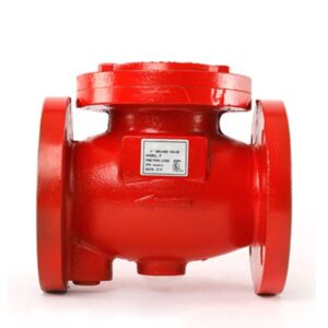
DELUGE VALVE
DELUGE VALVESpecifications
Body: Cast Iron, ASTM A48 Class 35 Cover : Cast Iron, ASTM A48
Class 35 Seat Rubber : NBR
SIZE : 2″ & 2-1/2″ & 3″
MAXIMUM PRESSURE : 12 Bar (175 psi)
Factory hydrostatic test pressure : (24.6 bar). 350PSI
MOUNTING : Vertical or Horizontal mounting
FLANGE CONNECTION : ANSI B 16.5 #150
FINISH : Fire red epoxy painted
APPROVAL : UL listed
Diaphragm Holder : AISI 304
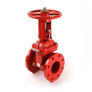
OS&Y GATE VALVE
OS&Y GATE VALVESpecifications
| Valve Standard | Conforms to AWWA C515, BS5163 |
| Working Pressure | 21 BARS/ 300PSI
Temperature : -10°c to 120°c Fusion bonded epoxy coated interior and exterior RAL3002 |
| Flanged Ends | ANSI B16.1 Class125/150,
EN1092-2 PN10/PN16 BS10 Table D/Table E |
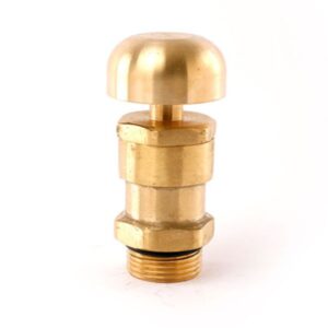
AIR RELEASE VALVE
AIR RELEASE VALVEFeatures
1) Greater air flow rates
2) Lightweight for easy transport and installation
3) Longer life and less maintenance
4) Easily disassembled for cleaning and replacing internal parts
5) Self – cleaning
Specifications
| Material | Copper Alloy |
| Testing pressure | 20 Bar (290 PSI) |
| Maximum working pressure | 12 Bar (175 PSI) |
| Inlet | BSP thread 1” |
| Temperature Range | 80°C (for water) |
| Temperature Range | 180°C(for stream) |
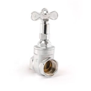
LOCK SHIELD VALVE
LOCK SHIELD VALVESpecifications
|
Maximum pressure conditions |
||
|
Max pressures (bar) |
20.0 bar on 100°c |
9.0 bar on 180°c |
|
Test pressure |
Shell 30.0 Bar |
Seat 22.0 bar |


